AIWA BMZ-K7D Service Manual PDF & Schematic Diagram
AIWA BMZ-K7D Service Manual PDF & Schematic Diagram
The AIWA BMZ-K7D Service Manual is a useful technical reference for identifying circuit sections, electronic components, connectors, wiring, and other service-related information for the BMZ-K7D system.
A service manual can be particularly helpful when troubleshooting a unit, checking circuit connections, identifying components, or carrying out technical inspection. However, the exact information available depends on the version of the service documentation.
Before using any schematic or service manual, confirm that the equipment is specifically identified as AIWA BMZ-K7D. Models with similar names or appearances may use different boards, components, or circuit revisions.
AIWA BMZ-K7D Schematic Diagram
The schematic diagram provides a technical representation of the electronic circuits used in the equipment. Depending on the available documentation, it may help with tracing connections between components and understanding individual circuit sections.
- Identifying electronic components and their reference numbers
- Tracing connections between circuit sections
- Checking connectors and wiring
- Understanding the relationship between different parts of the circuit
- Supporting troubleshooting and component-level inspection
- Comparing circuit information with the physical board
The schematic should always be used together with the correct model information and, where applicable, the appropriate board or chassis identification.
AIWA BMZ-K7D Service Manual Contents
The contents of an AIWA BMZ-K7D service manual can vary depending on the document version. Technical documentation may contain several types of information intended for service and maintenance purposes.
Block Diagram - RF SERVO Section

Block Diagram - CHANGER / VIDEO Section

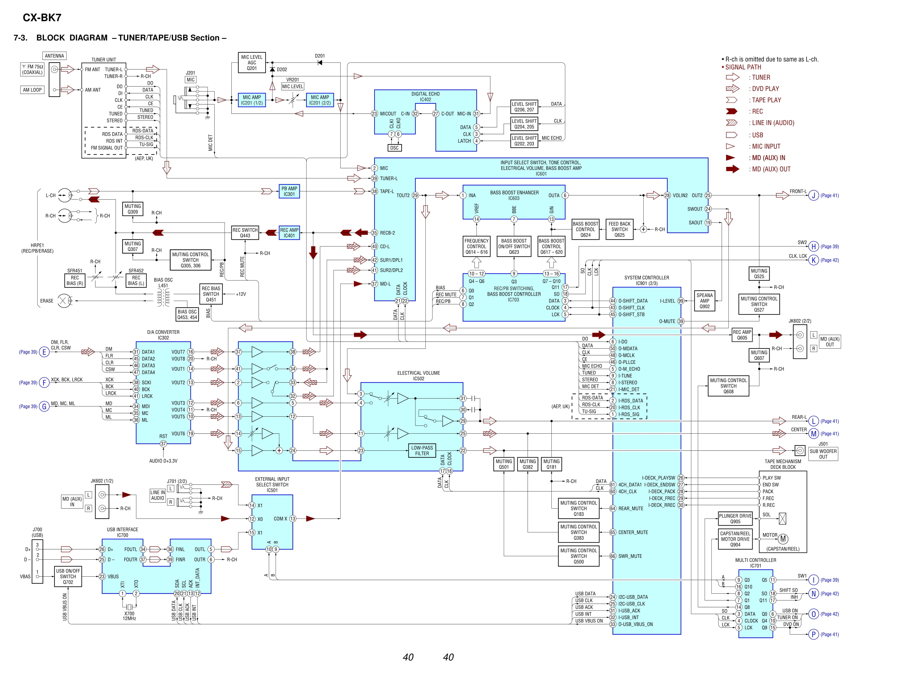
Block Diagram - TUNER / TAPE / USB Section
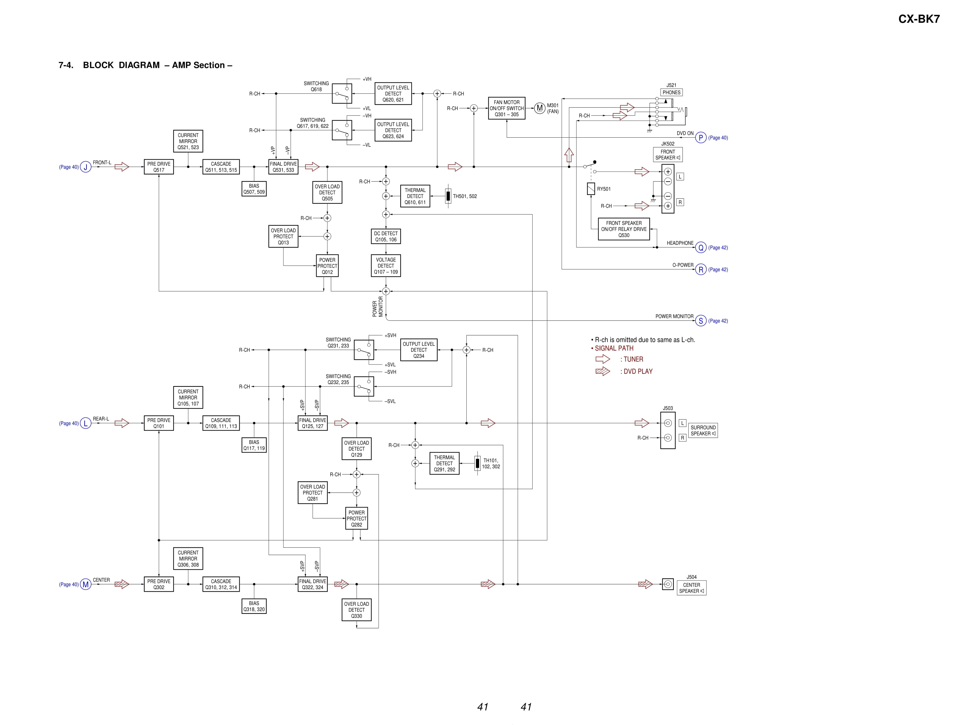
Block Diagram - AMP Section
Block Diagram - PANEL / POWER SUPPLY Section

Note for printed wiring boards and schematic diagrams

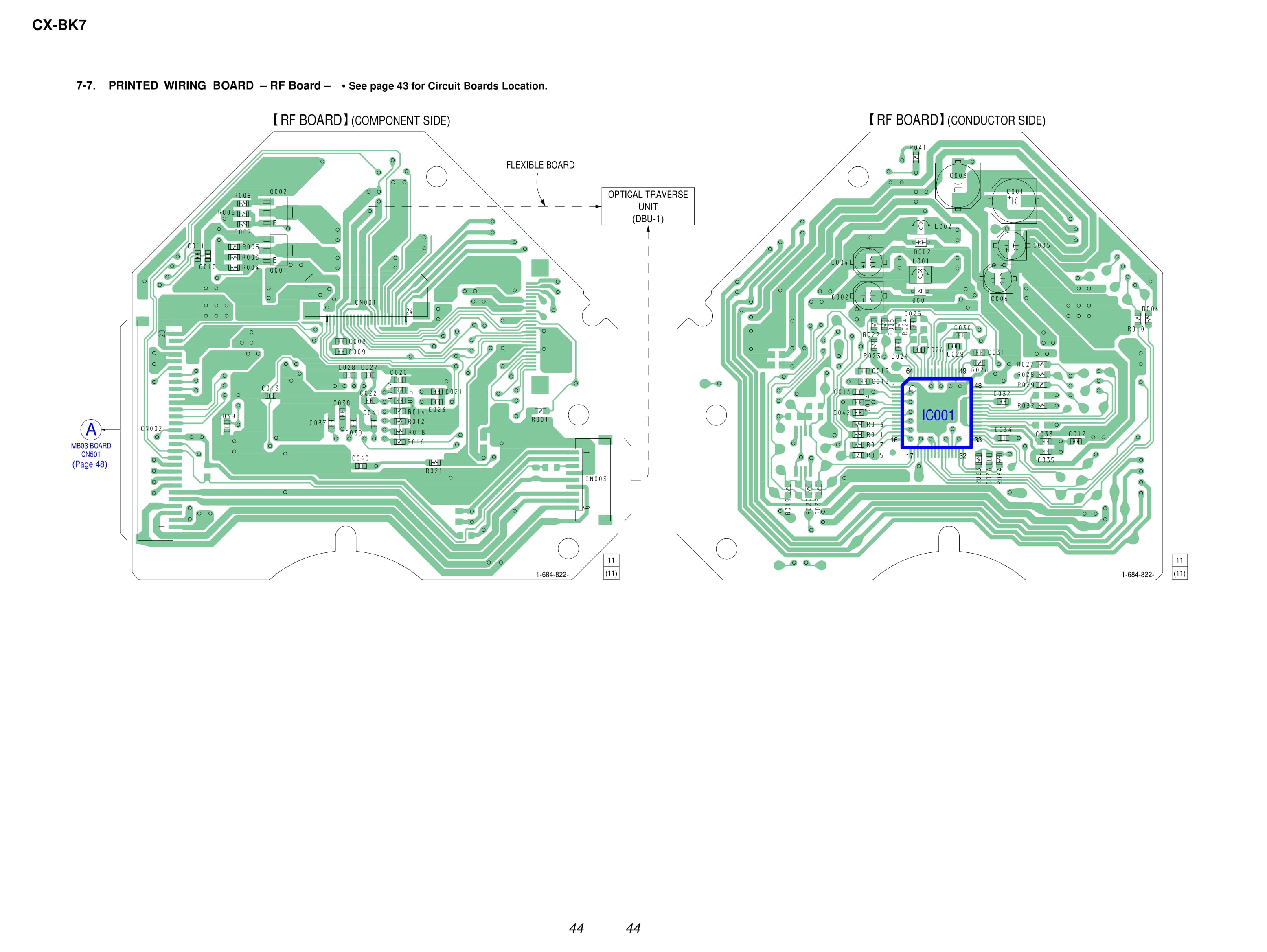
Printed Wiring Board - RF Board
Schematic Diagram - RF Board

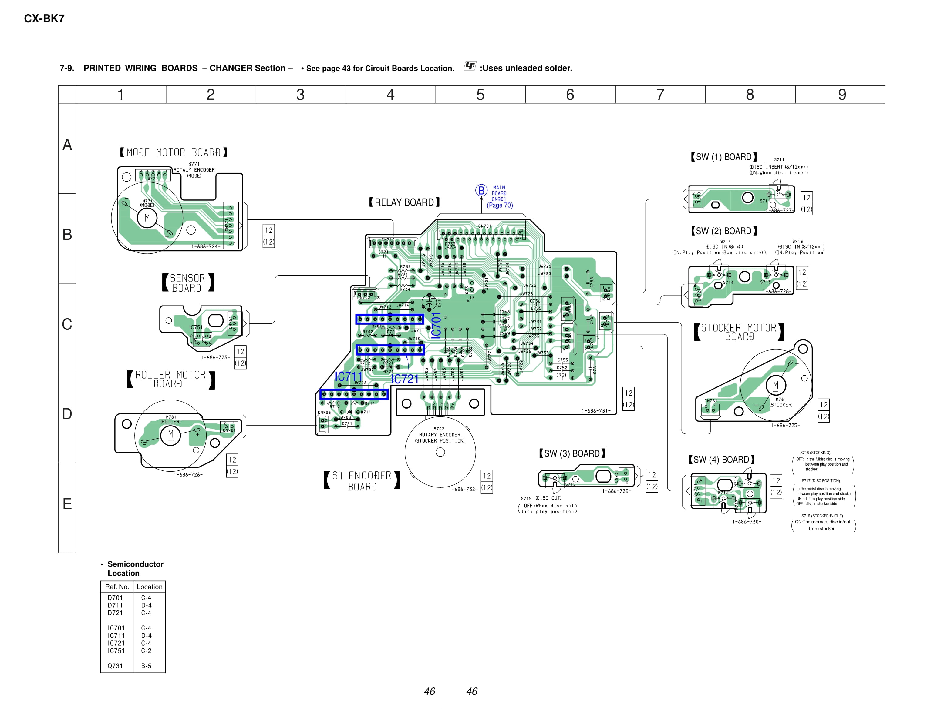
Printed Wiring Board - CHANGER Section
Schematic Diagram - CHANGER Section
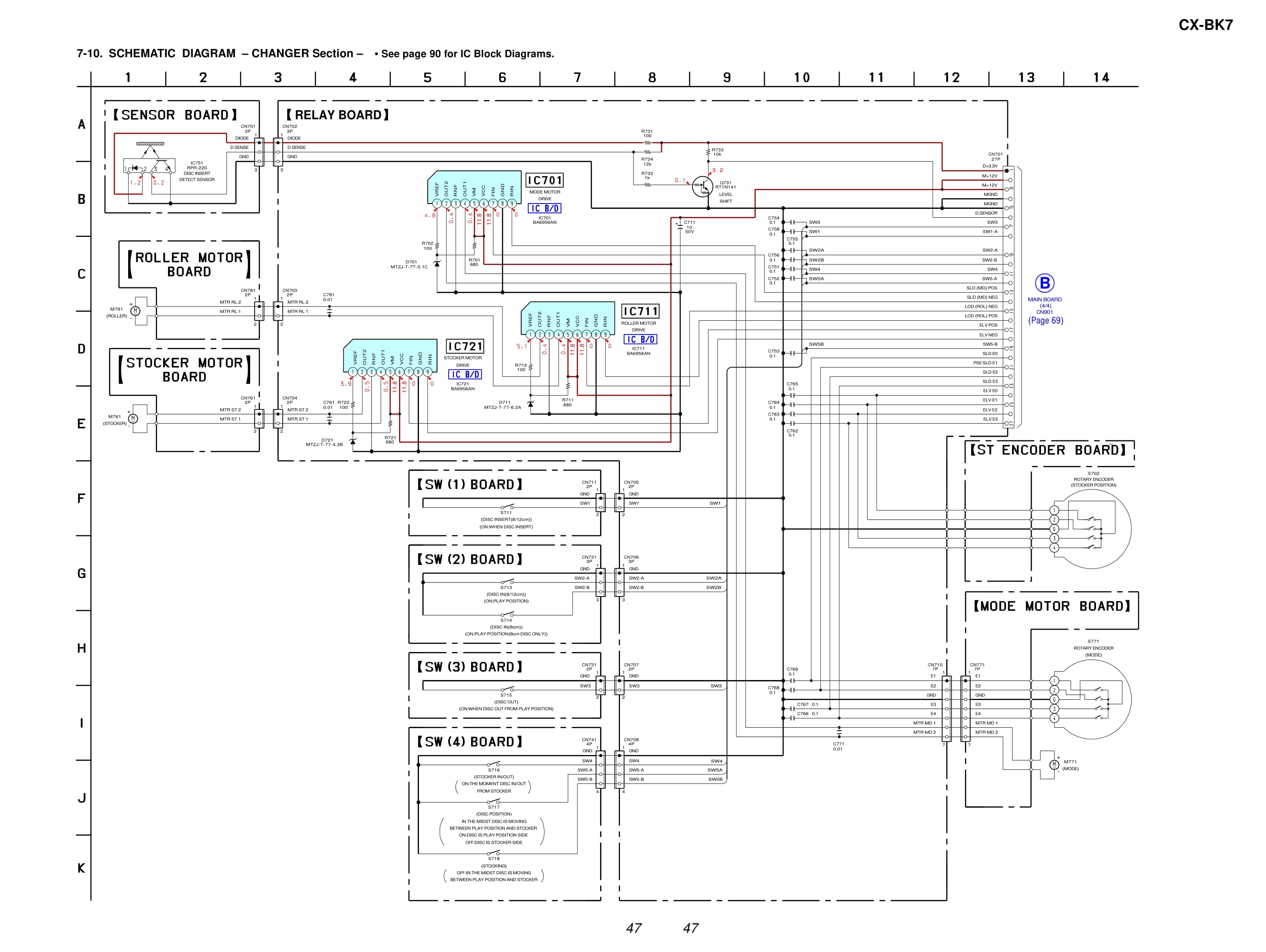
Printed Wiring Board - MB03 Board (Side A)

Printed Wiring Board - MB03 Board (Side B)

Schematic Diagram - MB03 Board (1/8)

Schematic Diagram - MB03 Board (2/8)

Schematic Diagram - MB03 Board (3/8)

Schematic Diagram - MB03 Board (4/8)
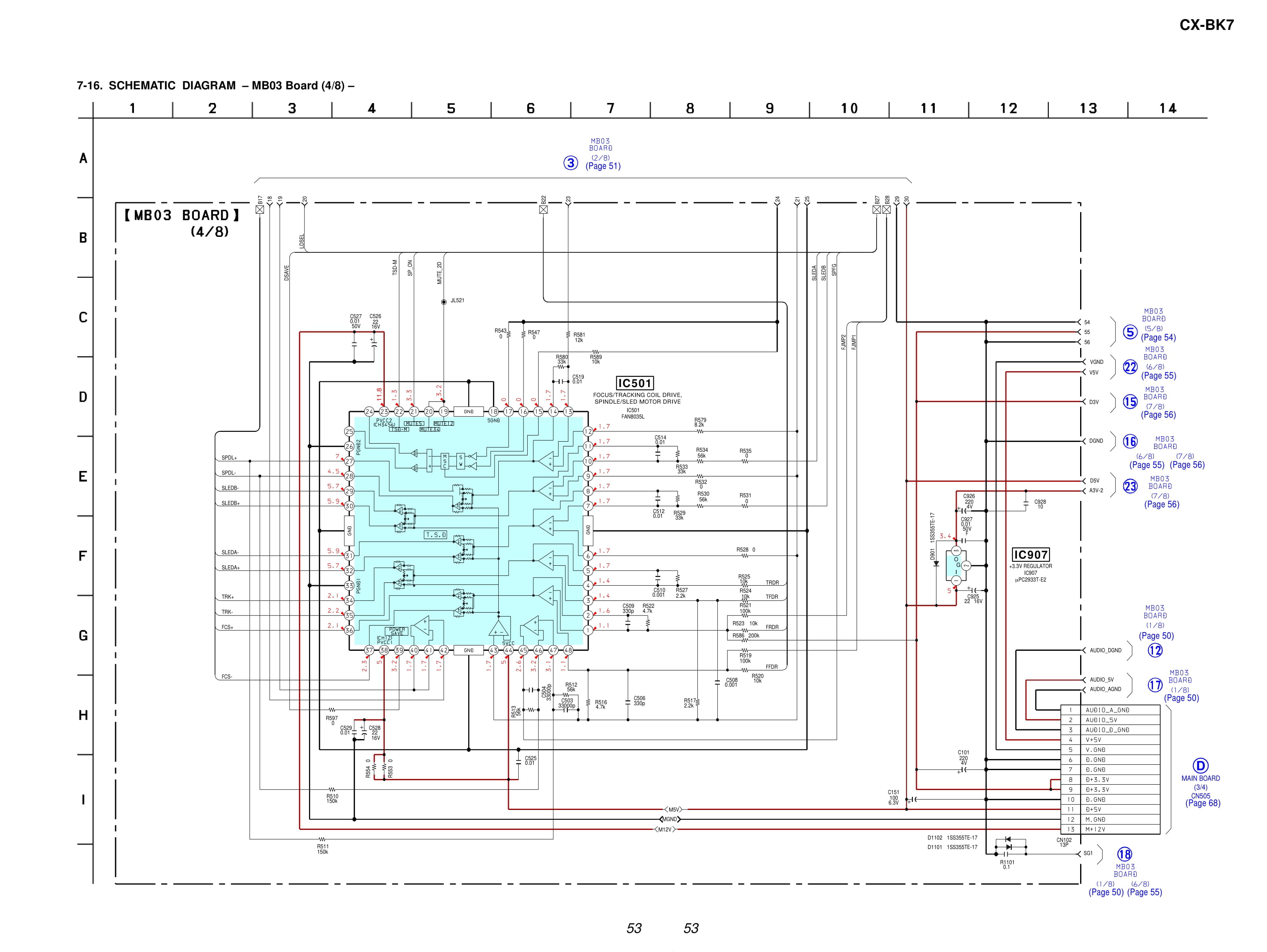
Schematic Diagram - MB03 Board (5/8)

Schematic Diagram - MB03 Board (6/8)
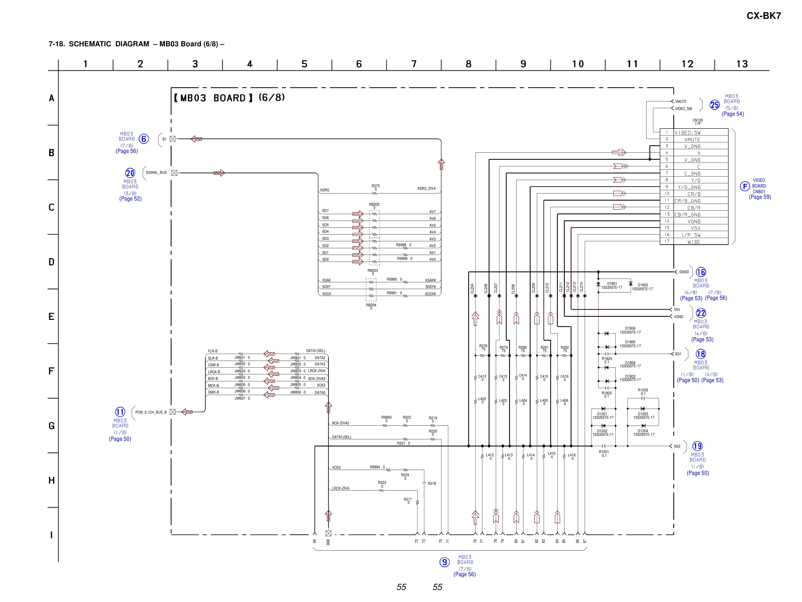
Schematic Diagram - MB03 Board (7/8)
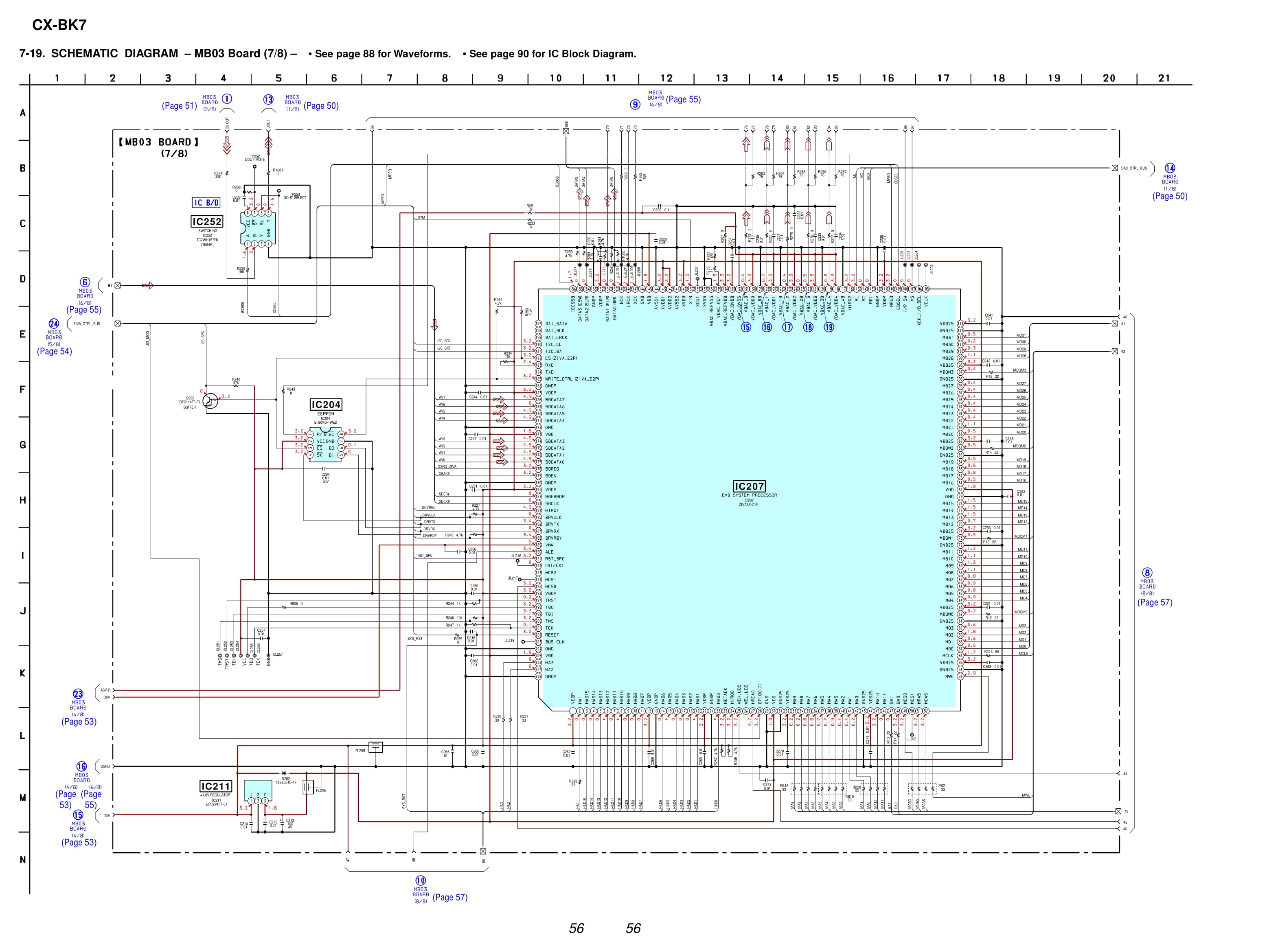
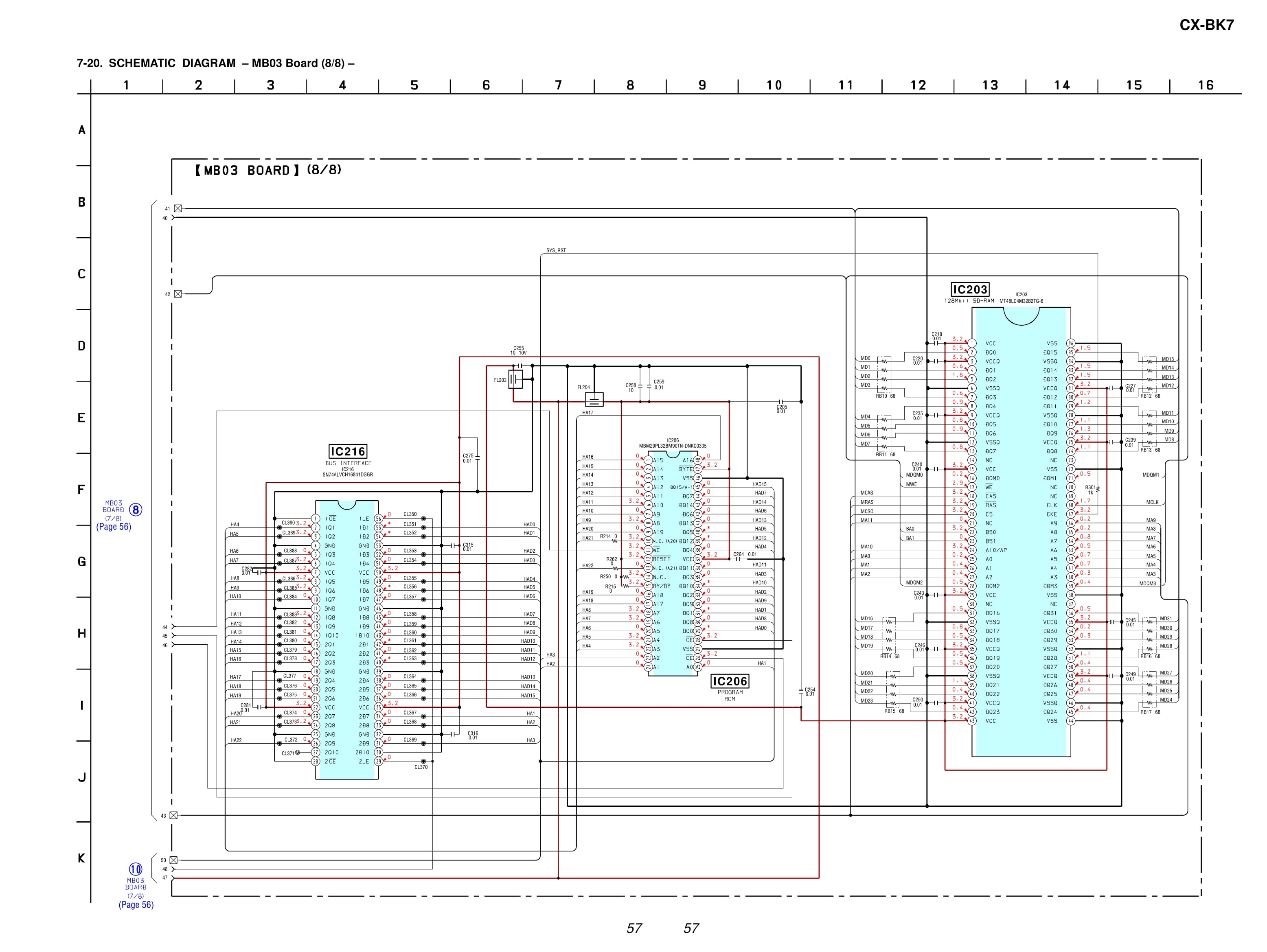
Schematic Diagram - MB03 Board (8/8)
Printed Wiring Board - VIDEO Board

Schematic Diagram - VIDEO Board

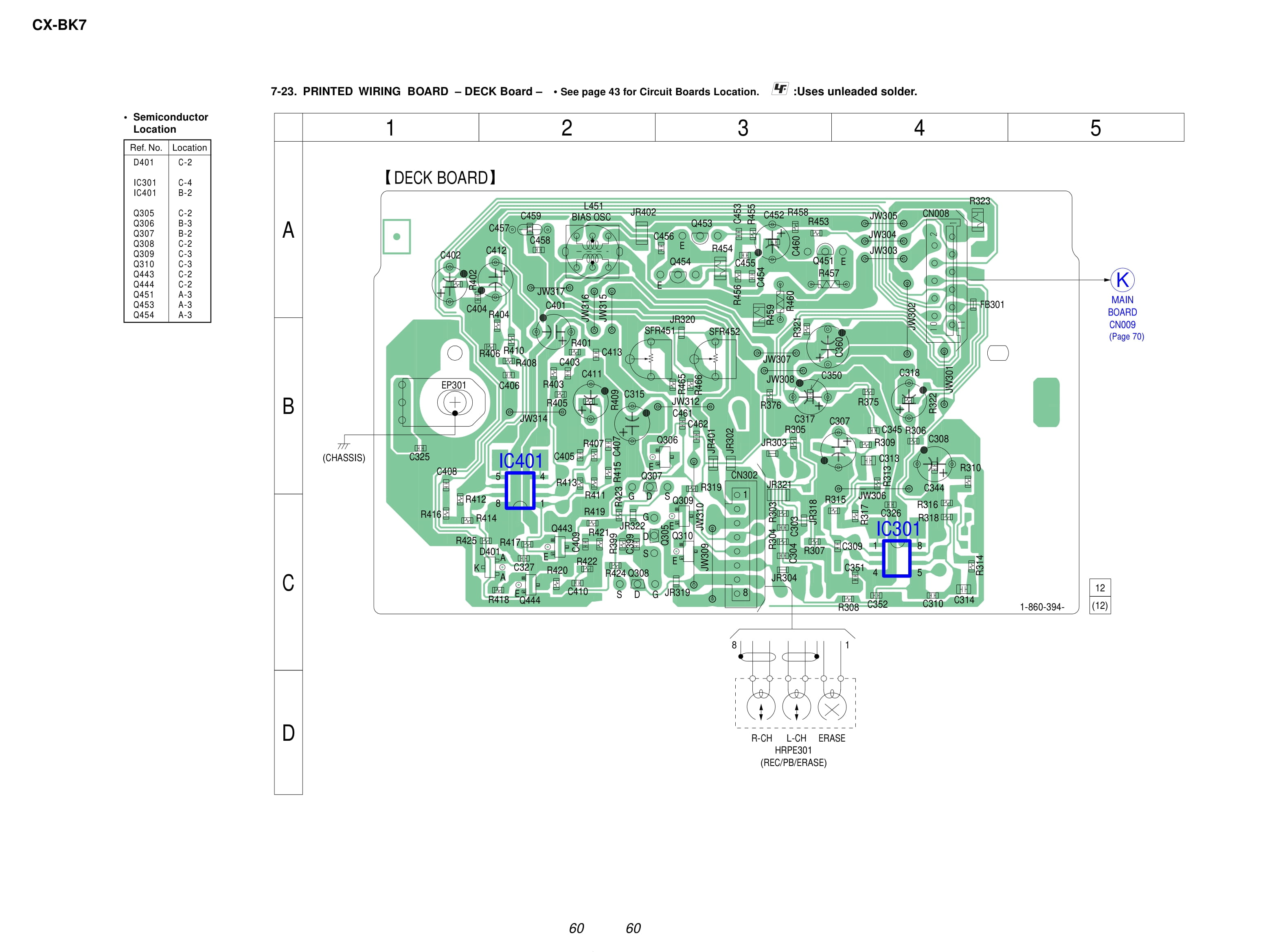
Printed Wiring Board - DECK Board
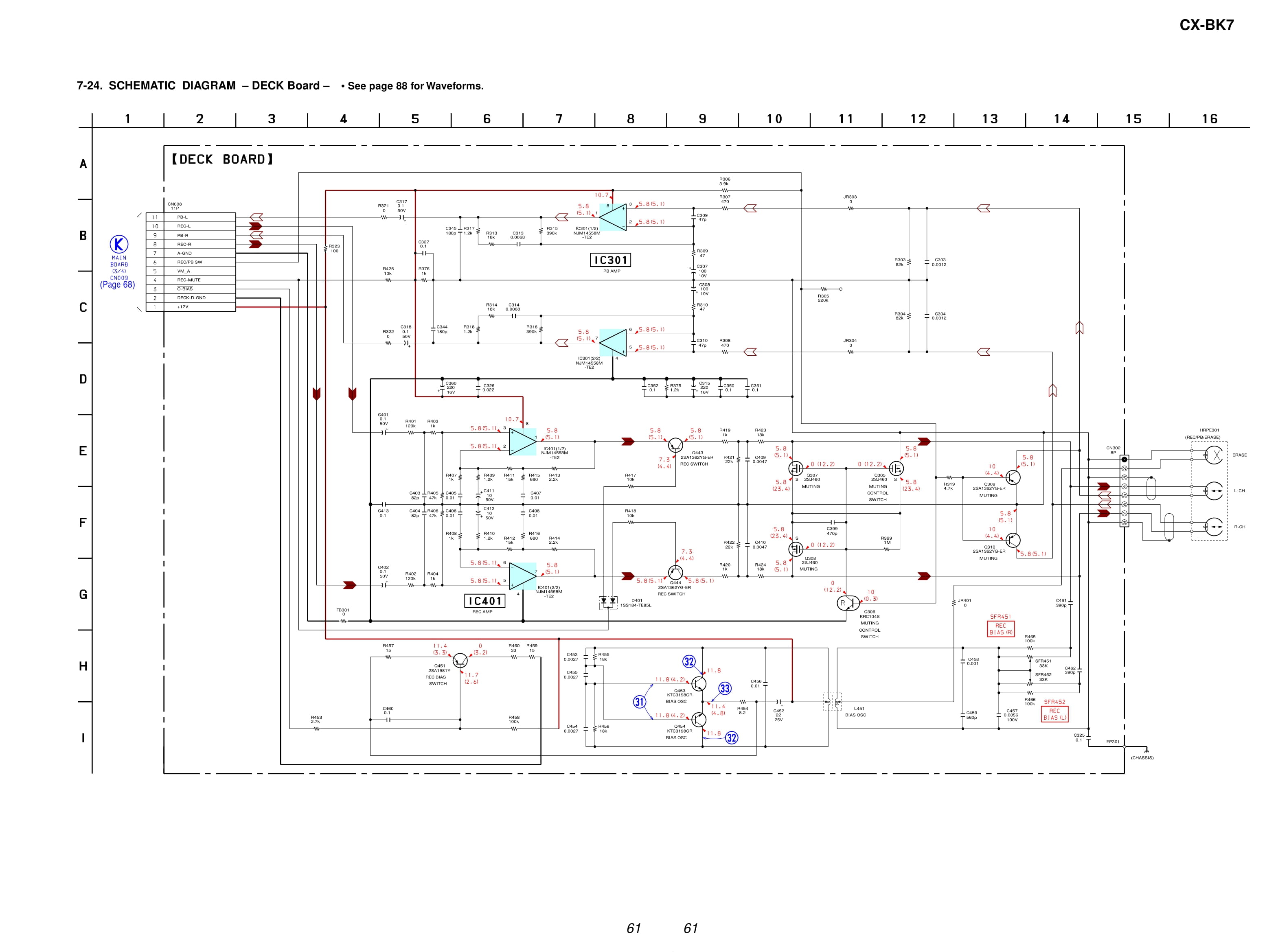
Schematic Diagram - DECK Board
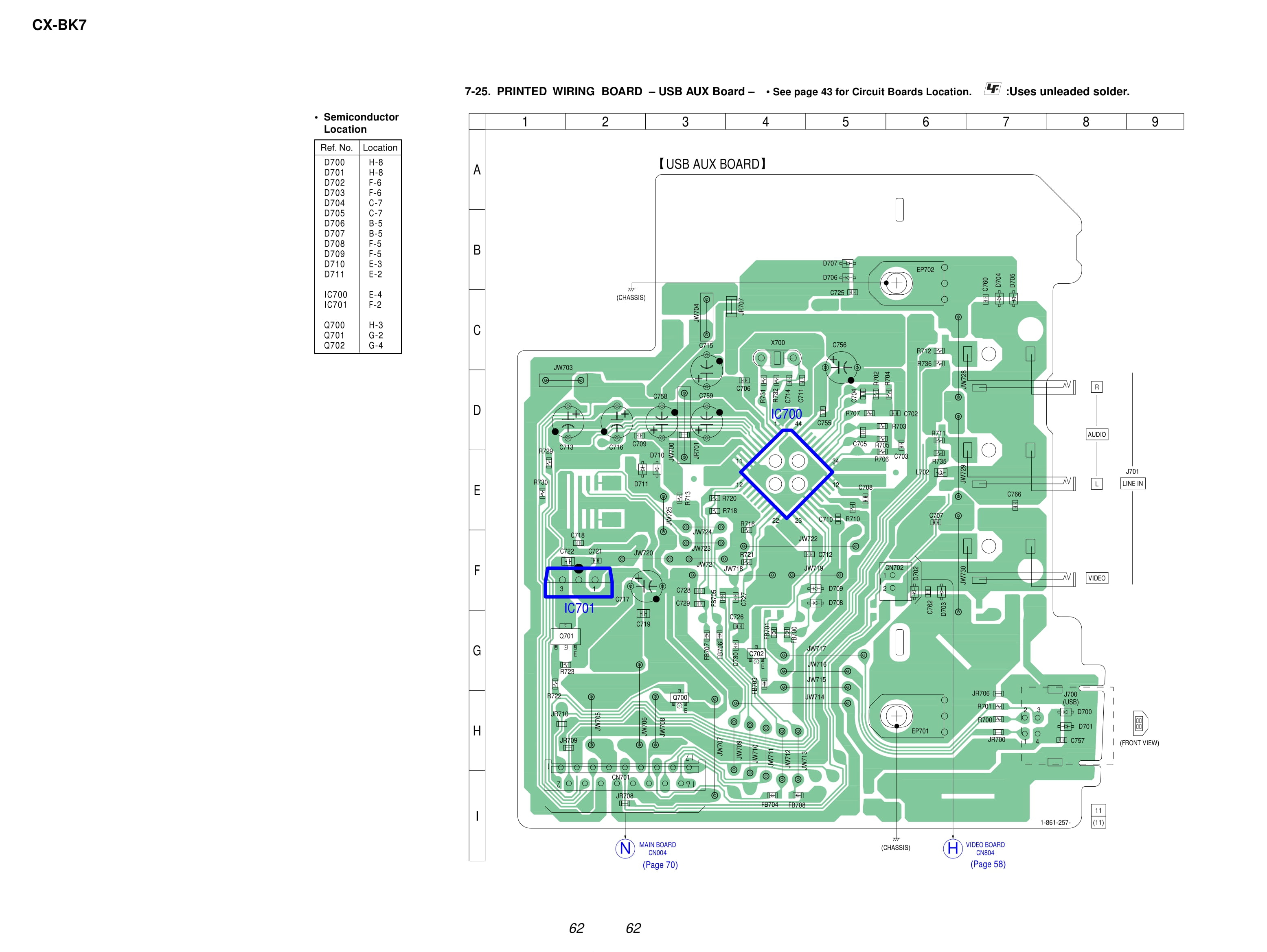
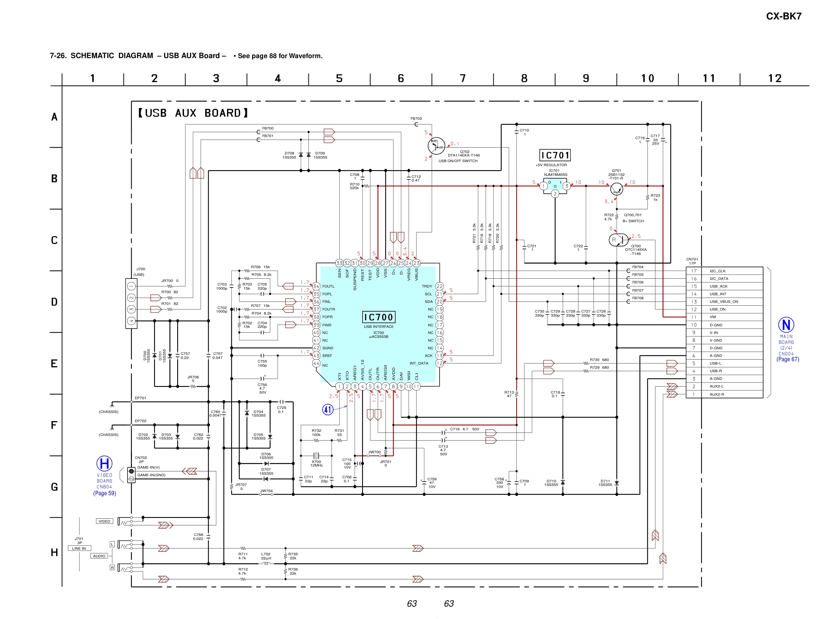
Printed Wiring Board - USB AUX Board
Schematic Diagram - USB AUX Board
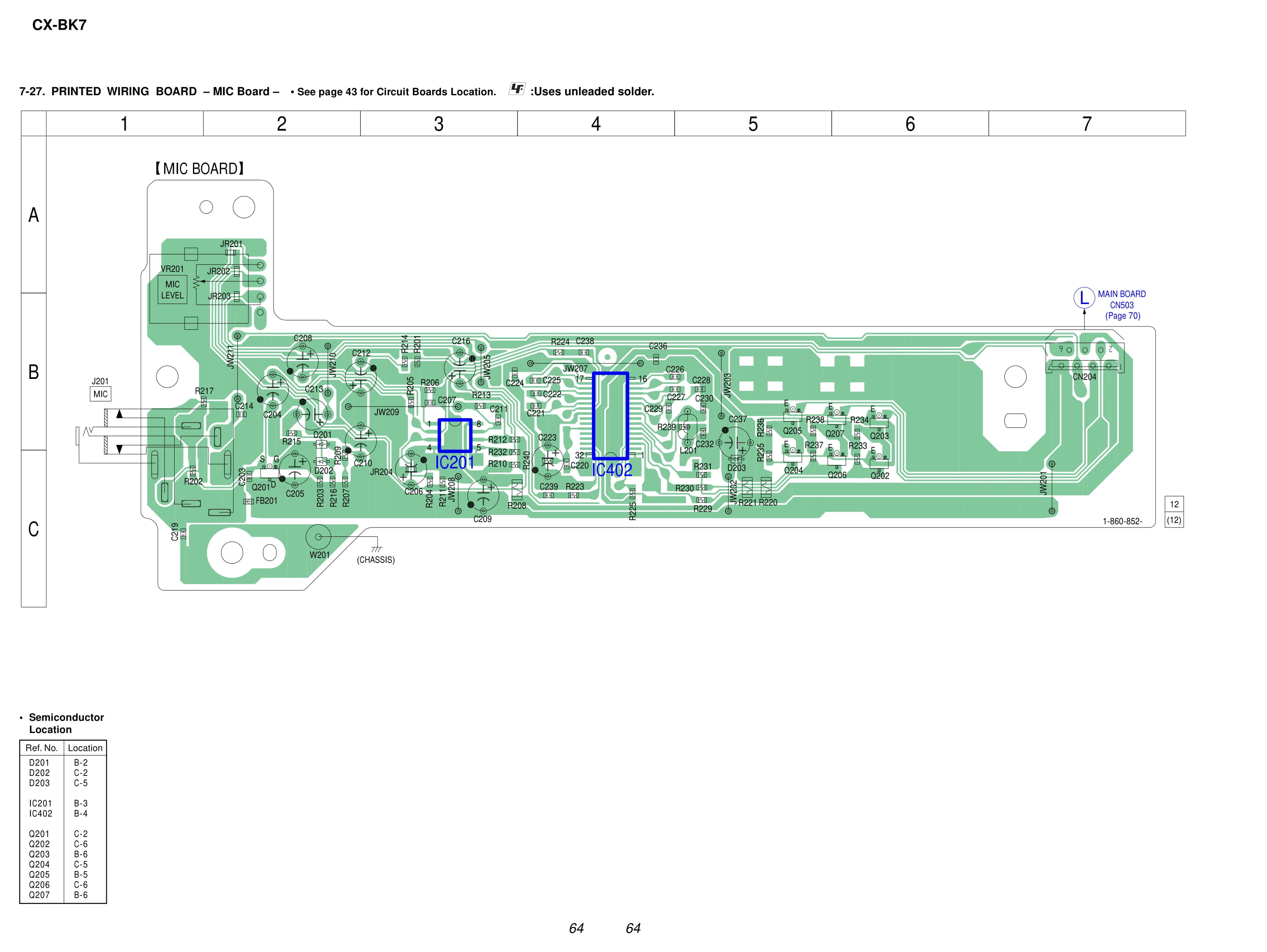
Printed Wiring Board - MIC Board
Schematic Diagram - MIC Board

Schematic Diagram - MAIN Board (1/4)

Schematic Diagram - MAIN Board (2/4)

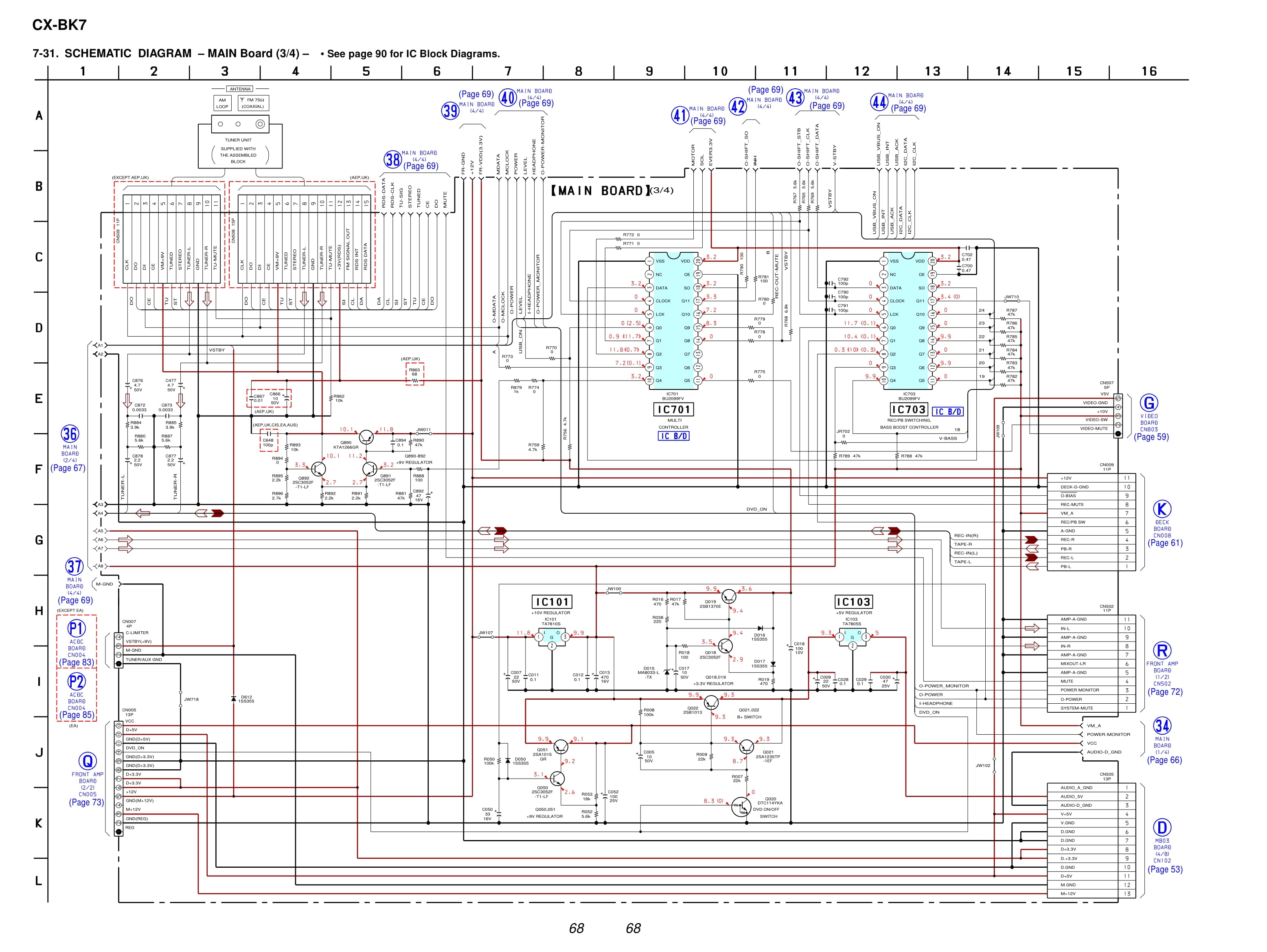
Schematic Diagram - MAIN Board (3/4)
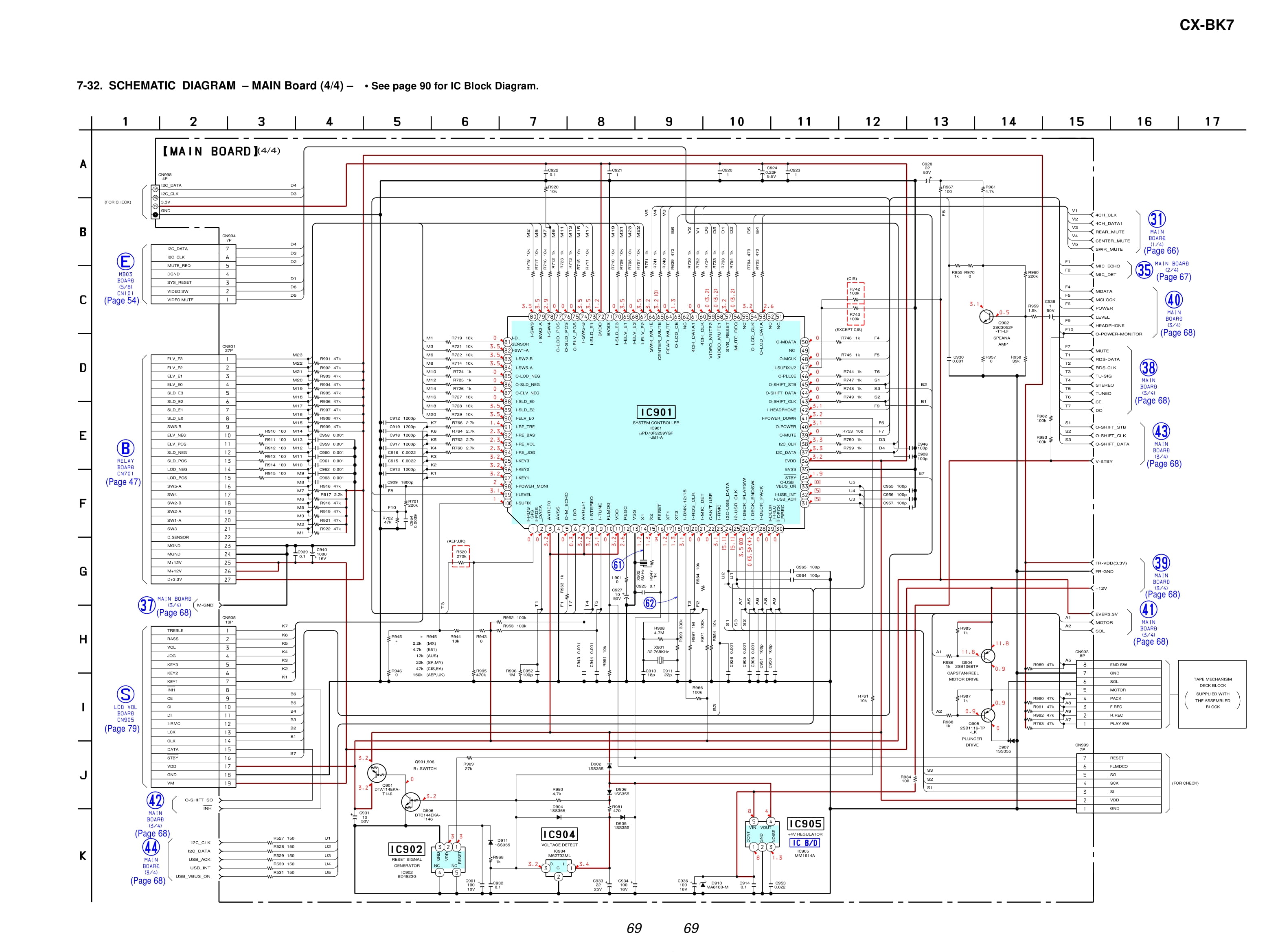
Schematic Diagram - MAIN Board (4/4)
Printed Wiring Board - MAIN Board

Printed Wiring Board - FRONT AMP Board

Schematic Diagram - FRONT AMP Board (1/2)

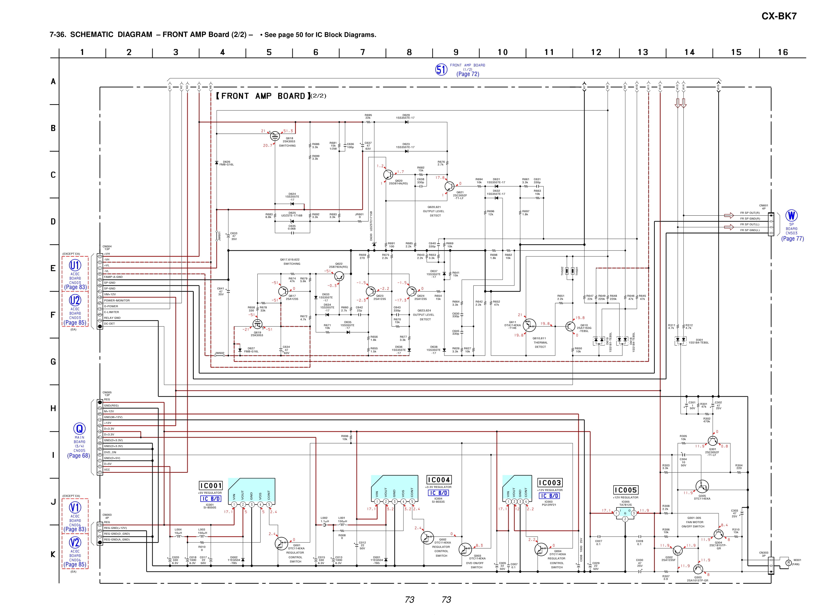
Schematic Diagram - FRONT AMP Board (2/2)
Printed Wiring Board - SURROUND AMP Board

Schematic Diagram - SURROUND AMP Board

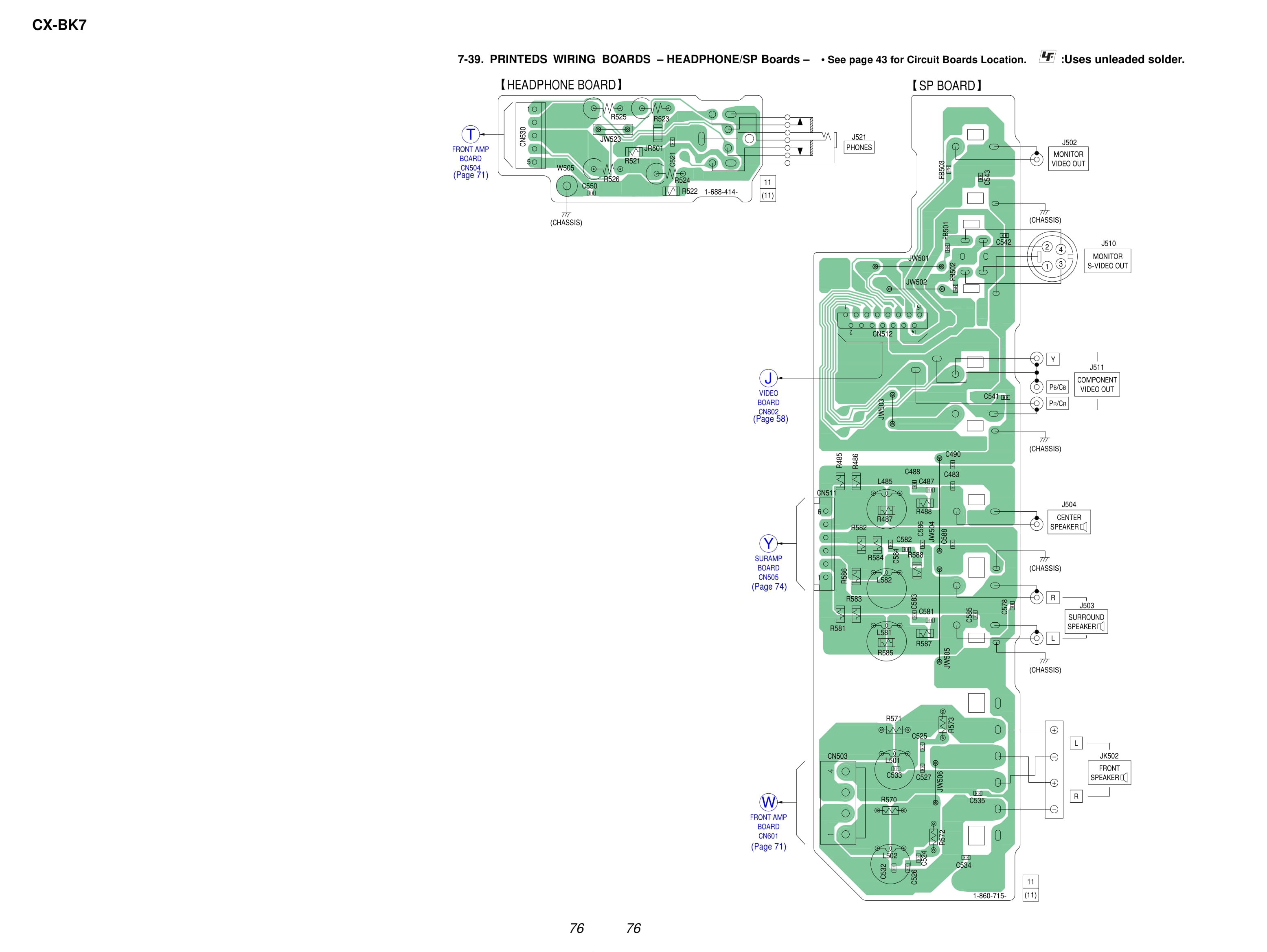
Printed Wiring Boards - HEADPHONE / SPEAKER Boards
Schematic Diagram - HEADPHONE / SPEAKER Boards

Printed Wiring Boards - PANEL Section(1/2)

Schematic Diagram - PANEL Section(1/2)

Printed Wiring Boards - PANEL Section(2/2)

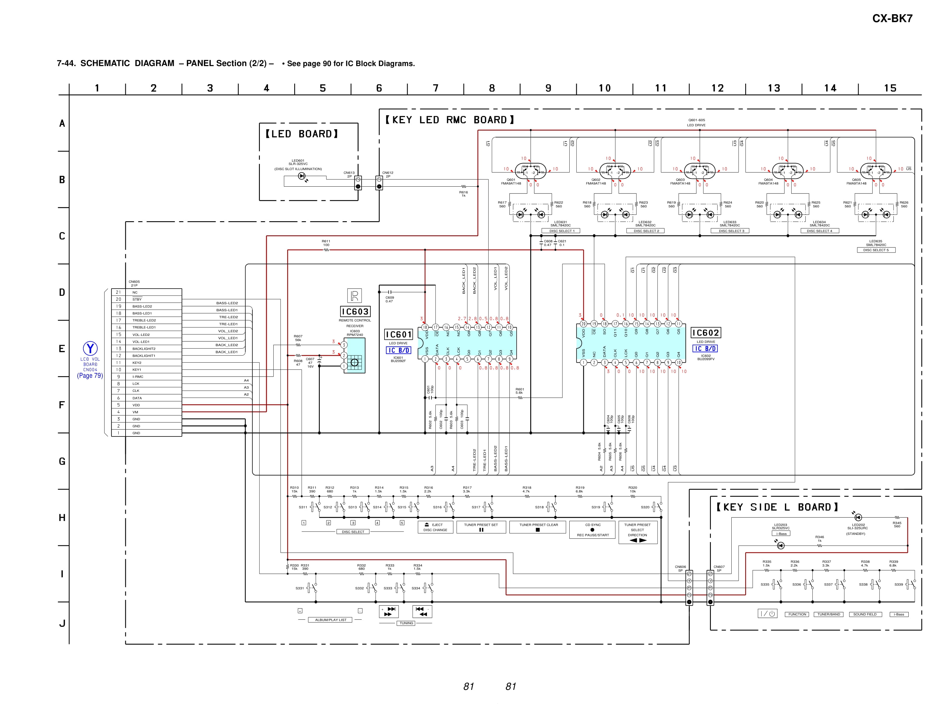
Schematic Diagram - PANEL Section(2/2)
Printed Wiring Board - AC/DC Board (Except Saudi Arabia Model)

Schematic Diagram - AC/DC Board (Except Saudi Arabia Model)

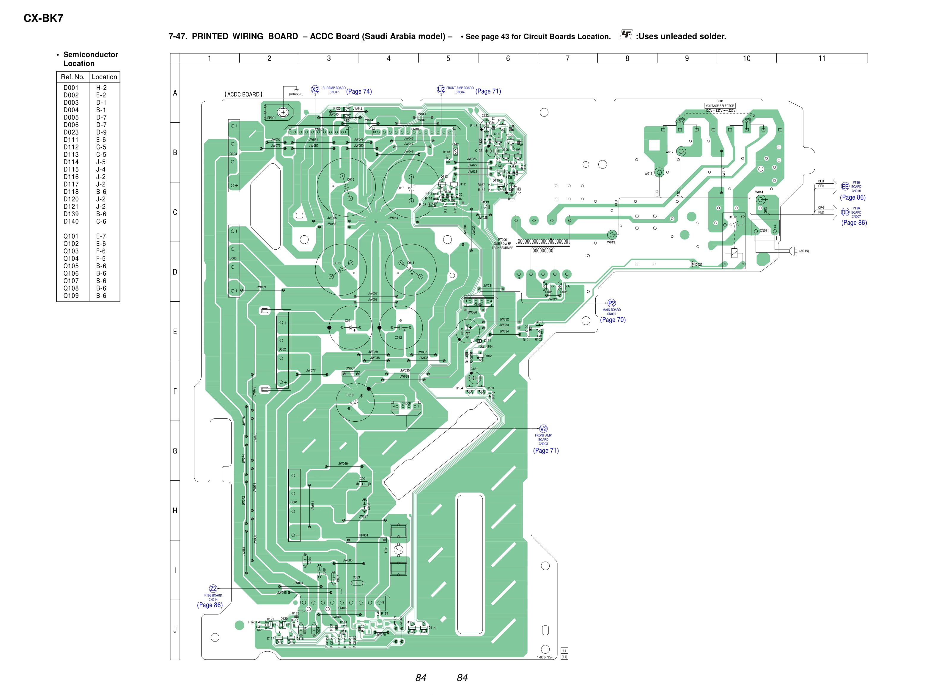
Printed Wiring Board - AC/DC Board (Saudi Arabia Model)
Schematic Diagram - AC/DC Board (Saudi Arabia Model)
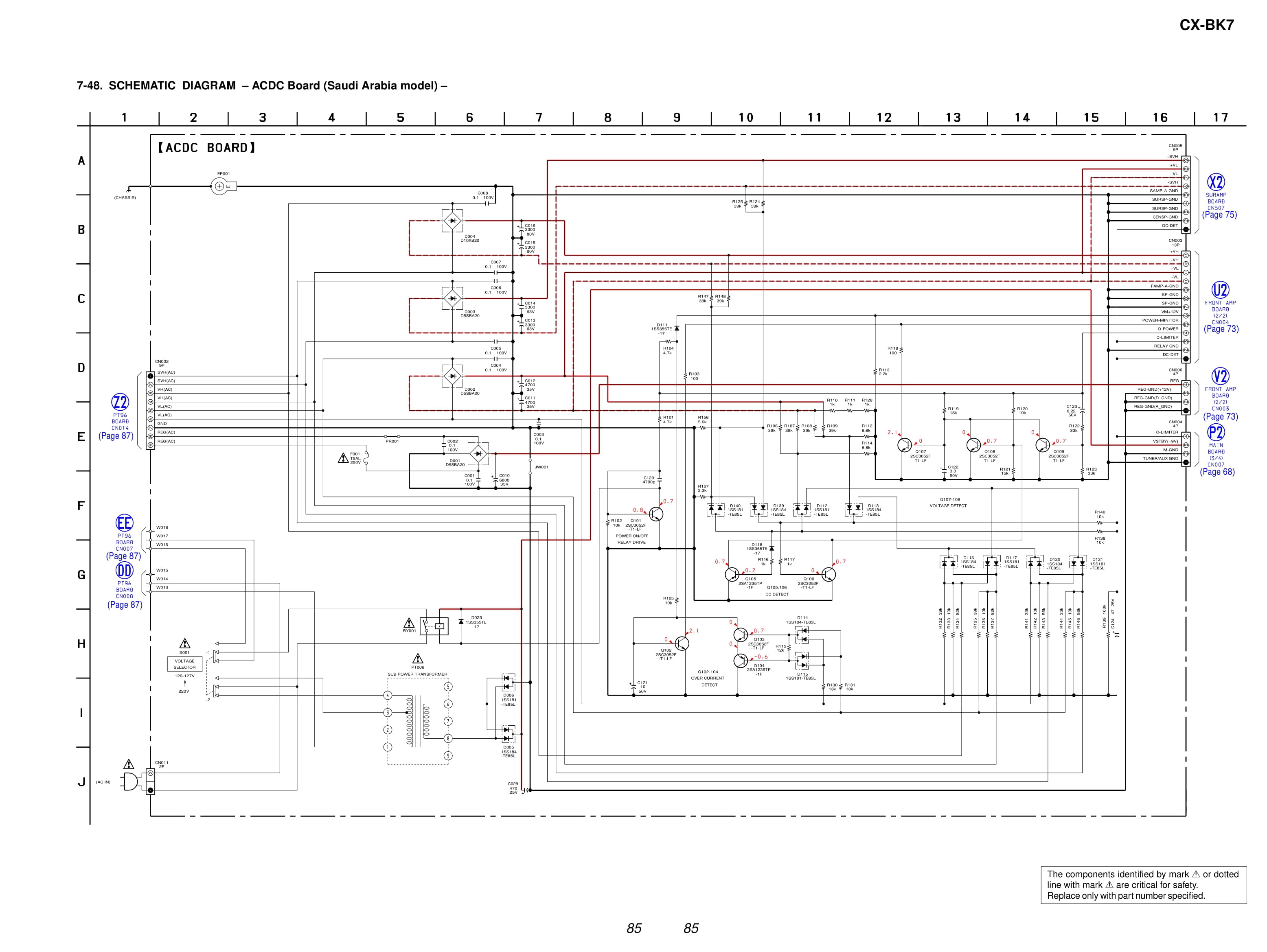
Printed Wiring Board - PT96 Board
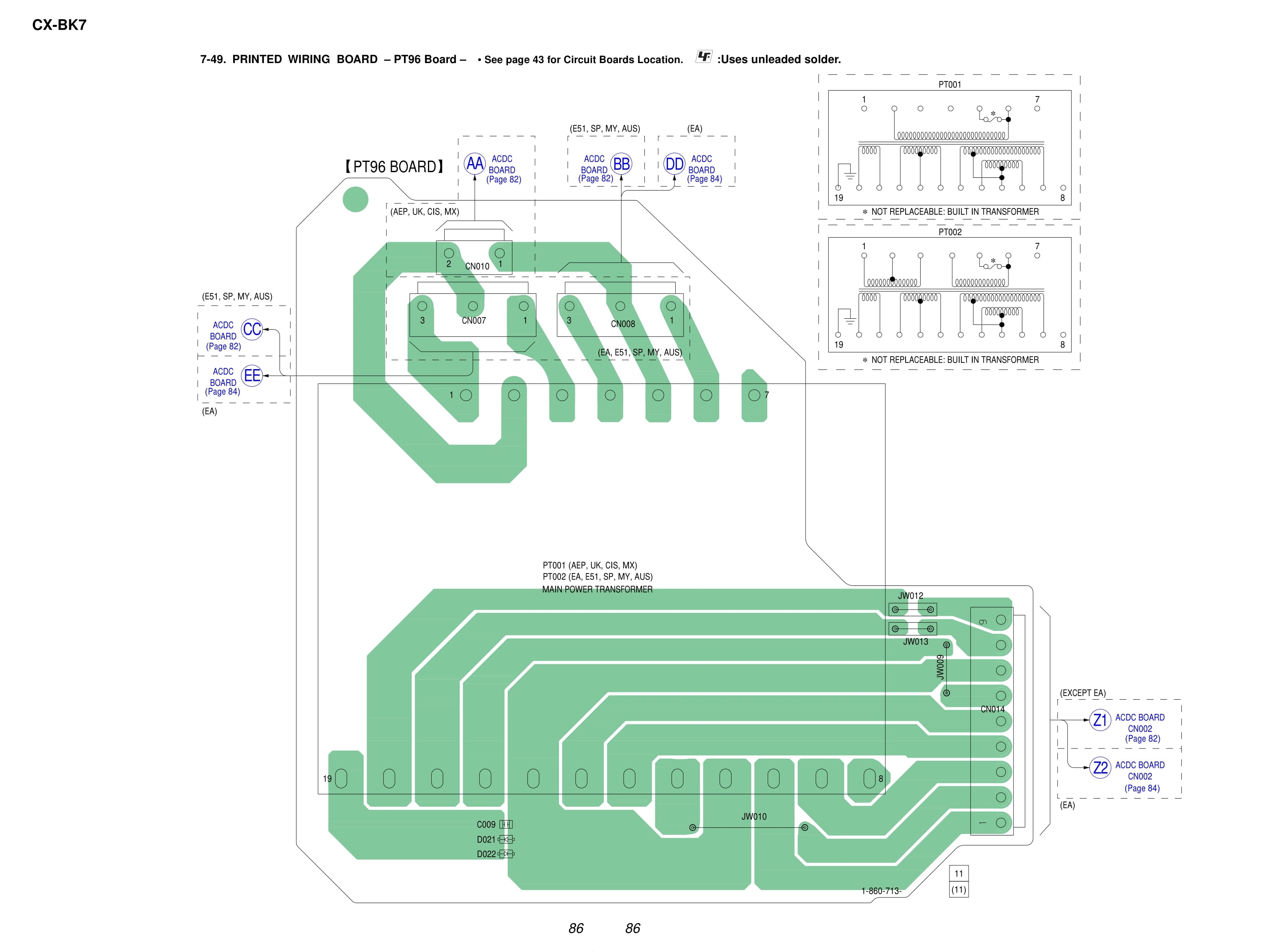
Schematic Diagram - PT96 Board

Waveforms - RF Board - MB03 Board

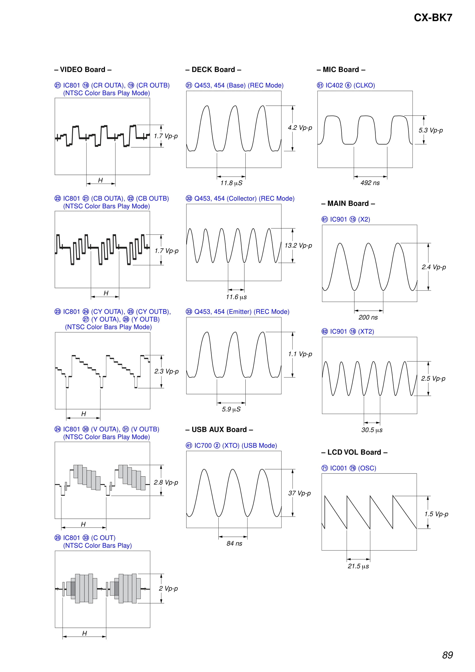
Waveforms - VIDEO Board - DECK Board - MIC Board
IC Block Diagram - RF Board - IC001 SP3723BDAOPM

IC Block Diagram - RELAY Board IC701, 711, 721 BA6956AN - MB03 Board IC252 TC7WH157FK (TE85R), IC302 PCM1608Y/2K

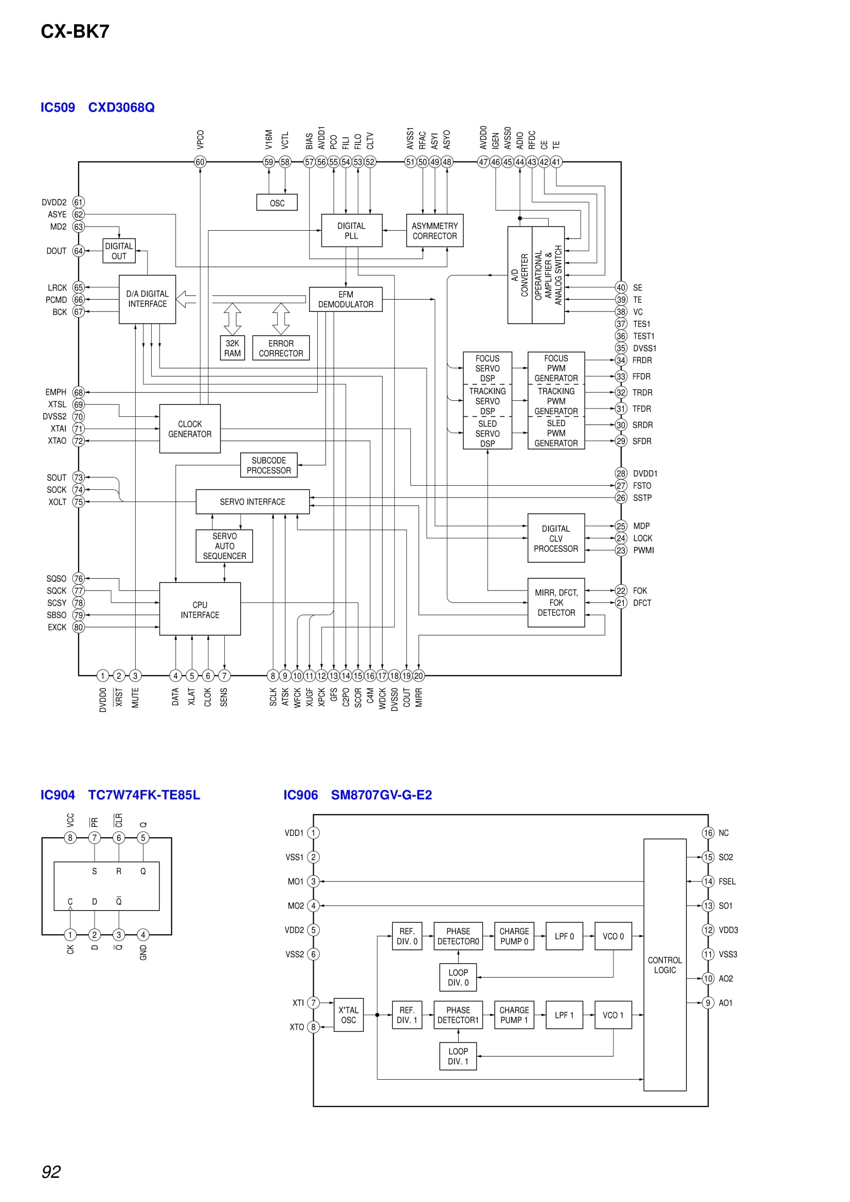
IC Block Diagram - IC509 CXD3068Q, IC904 TC7W74FK-TE85L, IC906 SM8707GV-G-E2
IC Block Diagram - IC701 TMC57929PGF-RDP

IC Block Diagram - VIDEO Board IC801 MM1568AJBE, IC802 NJM2244M-TE2 - MIC Board IC402 BU9262AFS

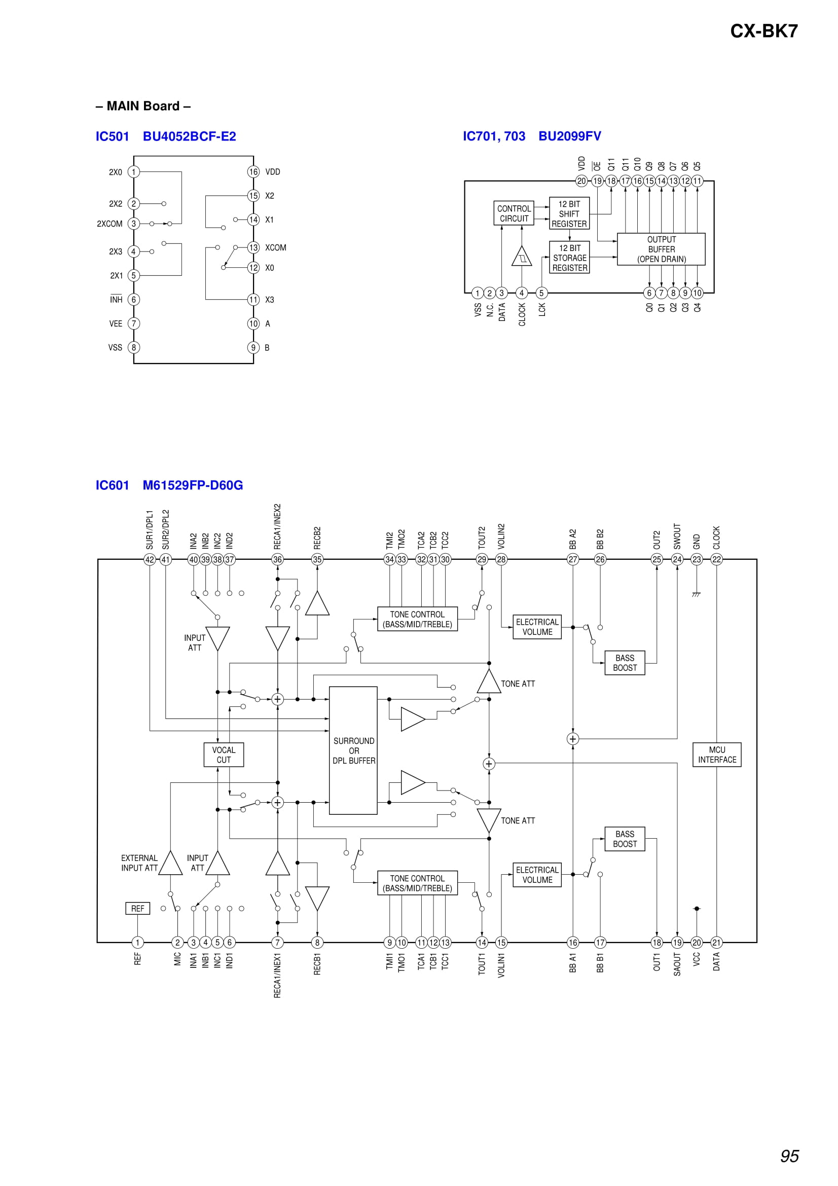
IC Block Diagram - MAIN Board IC501 BU4052BCF-E2, IC701 703 BU2099FV, IC601 M61529FP-D60G
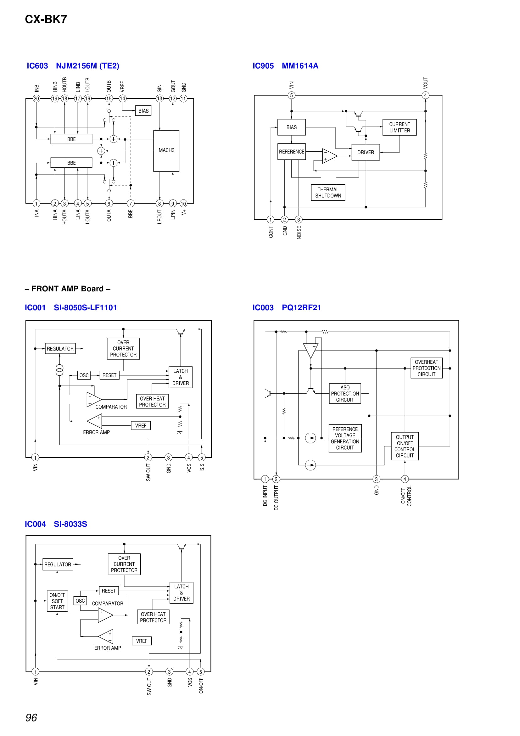
IC Block Diagram - IC603 NJM2156M (TE2), IC905 MM1614A - FRONT Amp IC001 SI-8050S-LF1101, IC003 PQ12RF21, IC004 SI-8033S
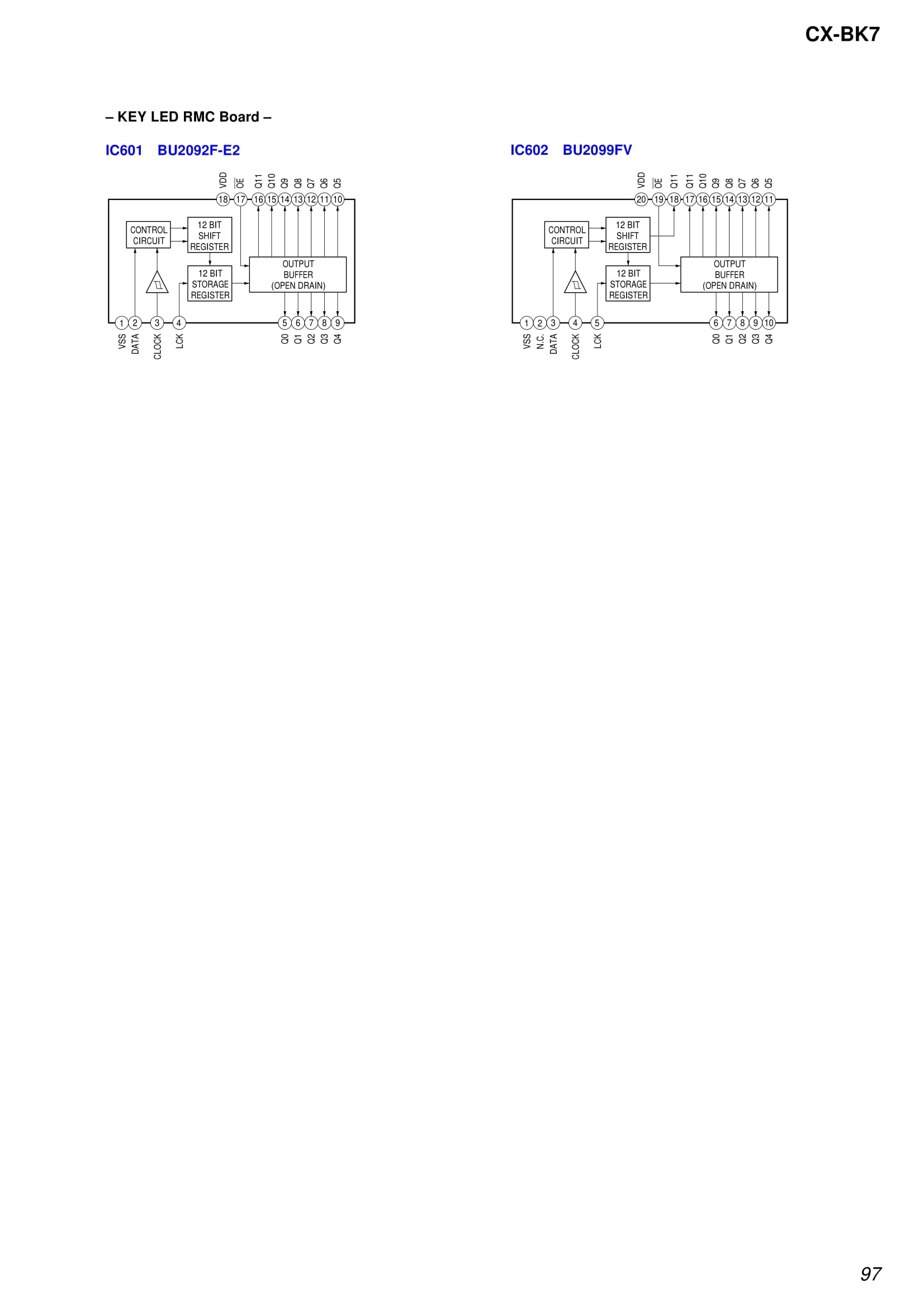
IC Block Diagram - KEY LED / REMOTE CONTROL IC601 BU2092F-E2, IC602 BU2099FV
How to Verify the BMZ-K7D Service Manual
Using the correct service documentation is important because audio equipment can have different hardware configurations even within a related product family.
Before relying on the manual, check the following:
1. Confirm the Brand
The equipment should be identified as AIWA. Check the nameplate, front panel, rear panel, or product label where applicable.
2. Confirm the Model Number
Make sure the model number is BMZ-K7D. Pay attention to the exact characters because similar model numbers may refer to different equipment.
3. Check Board or Chassis Information
If the equipment or documentation provides a board, chassis, or PCB number, compare that information with the service documentation.
4. Consider Hardware Revisions
Different production revisions may contain changes to components, boards, or circuit configurations. If a revision number is shown, verify it before using specific circuit information.
Download AIWA BMZ-K7D Service Manual PDF
The AIWA BMZ-K7D Service Manual PDF can be downloaded from the link provided on this page.
Document: AIWA BMZ-K7D Service Manual
Model: BMZ-K7D
Format: PDF
Download PDF
DOWNLOAD AIWA BMZ-K7D SERVICE MANUAL PDF
After opening the PDF, verify the model designation and other identifying information before using the document for technical work.
Using the Schematic for Troubleshooting
A schematic diagram can make it easier to understand how different circuit sections are connected. Rather than relying only on the physical appearance of a board, the diagram allows the technician to follow circuit paths and component relationships shown in the documentation.
For example, component reference numbers in the schematic can be compared with markings on the PCB. Connector designations can also be checked against the physical connectors on the equipment.
When troubleshooting, measurements should be made using appropriate procedures and equipment. The service documentation should be treated as a technical reference rather than assuming that every circuit value or configuration applies to every revision of the product.
AIWA BMZ-K7D Technical Documentation
The BMZ-K7D documentation can be useful for several types of technical work, including inspection, maintenance, troubleshooting, and repair.
Having the correct documentation can help reduce uncertainty when identifying components or tracing connections. It can also provide information that may not be obvious from the physical board alone.
For component replacement or circuit repair, always compare the information in the manual with the actual equipment before installing a replacement part.
Related AIWA Service Manuals
If you are researching other AIWA equipment, additional service manuals and schematic diagrams may be available for different models and product series.
Related documentation should be treated as separate technical references. A service manual for another AIWA model should not automatically be considered applicable to the BMZ-K7D, even if the equipment has a similar design or belongs to a related product family.
AIWA Service Manual and Schematic Diagram Collection
This page is part of a collection of technical documentation covering different AIWA service manuals, schematic diagrams, and circuit documentation.
To find documentation for another model, use the site's search function or browse the AIWA service manual category. Searching by the exact model number is recommended because it helps distinguish between models with similar names.
Important Note Before Repair
Service manuals and schematic diagrams contain technical information intended to support inspection and repair. Always verify the model, board identification, and document version before applying information from the manual to physical equipment.
If the documentation and the actual unit do not appear to match, stop and verify the correct service document rather than assuming that the differences are insignificant.
Frequently Asked Questions
What is the AIWA BMZ-K7D Service Manual?
The AIWA BMZ-K7D Service Manual is technical documentation associated with the BMZ-K7D system. Depending on the document version, it may contain circuit diagrams, component information, wiring details, and other service-related information.
Where can I download the AIWA BMZ-K7D Service Manual PDF?
The BMZ-K7D Service Manual PDF can be downloaded using the Download PDF link provided on this page.
Does the BMZ-K7D service manual include a schematic diagram?
The available documentation may include schematic or circuit diagrams, but the exact contents depend on the particular PDF version. Check the document itself to confirm the included sections.
Can I use another AIWA service manual for the BMZ-K7D?
It is not recommended to assume that another model's service manual is fully applicable to the BMZ-K7D. Always verify the exact model, board information, and hardware revision before using technical information from another document.
Final Check
Before starting troubleshooting or repair, confirm that the documentation matches AIWA BMZ-K7D and that any relevant board or revision information corresponds to the equipment being serviced.
Download the AIWA BMZ-K7D Service Manual PDF above and verify the model information in the document before using it as a technical reference.